41 digikey circuit diagram
Constant lighting style "block detector" 100 PIV, 2 amp bridge Digi-Key BR81D-ND $.98 ea or Radio Shack 276-1171 $1.59 ea. Unfortunately, we still have the major problems that (a) it won't light the lamp with a very low current can motor engine, (b) it won't light when running power is not attached to the block, and (c) when it does work, it will only light the one bulb (and cannot ... DC1568A (#2): 2 Cell, 8.2V, 2A Max, Solar. Demonstration Circuit 1568A is a 2A Monolithic Multi-Chemistry battery charger (Li-Ion/Polymer, LiFePO4, SLA, NiMH/NiCd) for solar power applications featuring the LT3652EDD. The LT3652 is a complete mid-power Li-Ion battery charger that can operate over a wide input voltage range.
Bldc Motor Wiring Diagram. Circuit diagram of the bldc motor brushless dc nidec corporation power and control motors three phase drive what are controller using wiring with sensorless pic bld500 48v 500w driver. Circuit Diagram Of The Bldc Motor Scientific. How To Power And Control Brushless Dc Motors Digikey. Schematic Diagram Of A Three Phase ...

Digikey circuit diagram
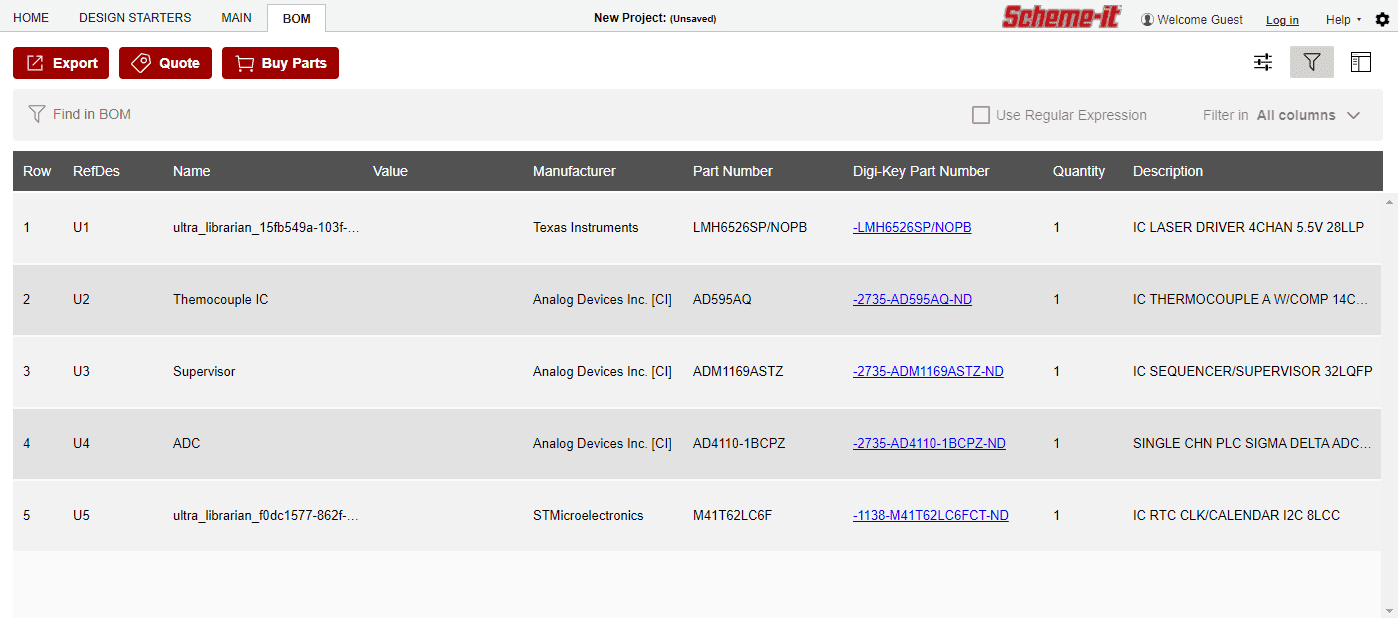
Digi-Key customers in the United States can select from a range of delivery options, including Ground shipping at $6.99 and 2-Day at $12.99 ... Scheme-it is an online schematic and block diagramming tool for designing and sharing electronic circuit diagrams. Design at the schematic, block, or board level. Learn More . Scheme-it - Schematic Drawing and Block Diagramming Made Easy. Scheme-it is an online schematic and diagramming tool that allows anyone to design and share electronic circuit diagrams.The tool includes a comprehensive electronic symbol library and an integrated Digi-Key component catalog that allows for a wide range of circuit designs. The amplifier circuit diagram shows a 2.5W * 2 stereo amplifier. You can also make a 5W mono amplifier out of it. (Check out the TEA2025 datasheet for more information on that) On the input side, you should use a dual potentiometer. A dual potmeter allows you to connect both the left and right channels on one potentiometer.
Digikey circuit diagram. 74C922 IC. This is a 16-key encoder. You can pick them up from mouser.com or digikey.com for around $5. I got a handful at my local electronics shop for $0.95 each. 2 x 0.1 uF tantalum capacitors. You can probably get away with ceramic if you have them already. DLO7135 Dot matrix LED. This is one SWEEET component. Circuit Optical cable E/O converter Receiving Photodiode Circuit O/E converter Fiber-optic link optical connector Electrical output signal Receiving Module optical connector LED TOSLINK™ is a family of data transmission devices that use optical signals instead of electrical signals. Because TOSLINK uses an optical fiber cable as Circuit Works Conductive Ink Pen - part number 5168-2200ST $11.95 Circuit Works Overcoat Pen - part number 5168-3300G $ 9.95 Surface mount resistors (size:0805 1/10 watt 4.7K ohms) - part number 260-4.7K $2.40 per 100 Instructions (all steps refer to the wheelset drawing below): Fritzing diagram of HX711 amplifier connected to a RedBoard Now, if you would like to set up four single load sensors with our combinator board and amplifier, connect the five pins labeled RED, BLK, WHT, GRN, YLW to the matching pins on the HX711. Next, connect each of the four load sensors to the following pins: • Red → + •Black → -
SmartDraw is a free software designed to create diagrams for electronic circuits. Ad Review the Best Drawing Software for 2021. And there is a lot of other free 2D CAD software that you can use for schematic design. SmartDraws schematic diagram software is easy to use. I think your diagram is. Best program for drawing diagrams on Windows and Mac. Circuit Types:Jacks normally have through circuits, shunt circuits, and/or isolated switching circuits, either individually or in various combinations.The chart below shows schematics of 39 common jacks - many more combinations are possible, but these are the most commonly used. A basic description of the Digi-Key offers 12.6M + products from 2,000+ manufacturers. Large in-stock quantities able to ship same day. Paypal accepted, order online today! However, if Digikey has the switch shown in your diagram in toggle, right angle PCB mounting format I would like to purchase some. SP3T toggle switches seem to be very rare. Paul_Burmeister November 8, 2018, 8:53pm
The Schematic Diagram: A Basic Element of Circuit Design. by Anne Mahaffey Download PDF. There seems to be a limitless amount of information that can be learned in the field of electrical engineering. One of the most essential skills for an electrical engineer is the ability to read and create schematics. Before you start learning Ohm's law ... Wiring Diagram (Bottom V i e w ) Code 2 T73L1D15-05 "L" denotes tape sealed enclosure T73S1D15-05 "S" denotes permanently sealed enclosure. T73S5D54-12 "5" denotes UL873 spacing. T73S5D24-12B "B" denotes Class B (130oC) coil. PRINTED CIRCUIT BOARD RELAYS RKA Series Printed Circuit Board Relay F E AT U R E S • 10Arating • Immersion cleanable ... Robert_Fay November 14, 2017, 5:21pm #2. @Billy, Currently you are only able to draw vertical and horizontal lines in Scheme-it. This is fairly standard as it helps create clear ans easily readable diagrams. Once you move to designing a pcb layout there is often options in the design software for diagonal traces to help with board layout. SparkFun Opto-isolator Breakout BOB-09118 ROHS 3 images are CC BY-NC-SA 3.0 3D Download: STL, Blender Description: This is a board designed for opto-isolation. This board is helpful for connecting digital systems (like a 5V microcontroller) to a high-voltage or noisy
Scheme-it is a free online schematic. Welcome to the Scheme-it Free Online Schematic and Diagramming Tool DigiKey Electronics Scheme-it project. House Wiring Diagram Symbols Electrical Symbols Electrical Wiring Diagram Electrical Circuit Diagram Download TinyCAD for free. Electrical schematic drawing free. TinyCAD is a program for drawing electrical circuit diagrams commonly. Light Box Wiring ...
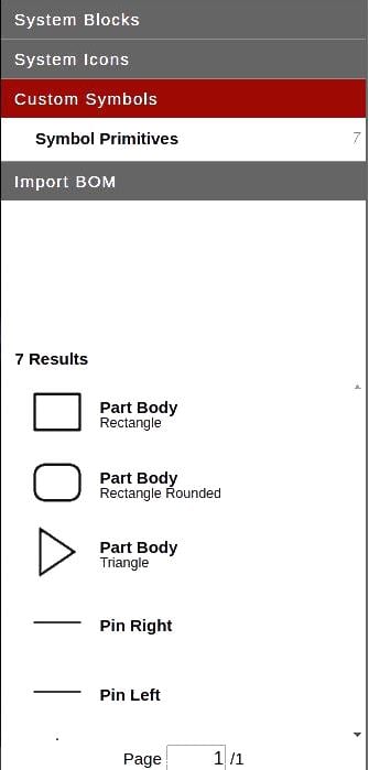
Welcome to the Scheme-it | Free Online Schematic and Diagramming Tool | DigiKey Electronics Scheme-it project. Scheme-it is a free online schematic drawing tool that will allow you to produce professional looking schematic diagrams, add corresponding part numbers, and share your schematic with others.
Colour code of 500 ohm resistor. Resistor color code band 1 band 2 band 322 ohm r22 red red silver27 ohm r27 red purple silver33 ohm r33 orange orange silver. 4 band resistor color code calculator. Brown black yellow gold. A separate code the 25 pair color code is used to identify wires in some telecommunications cables.
Wiring diagram AQV10 Series 1a DC A AQV11 Series AQV20 Series 1a AC/DC A DC B Can be also connected as 2 Form A type. (However, the sum of the continuous load current should not exceed the absolute maximum rating.) DC C 1 2 3 6 5 4 Terminal 3 cannot be used, since it is in the in-
Intelligent Wiring Diagram Formatting SmartDraws diagramming tools connect the components of your wiring diagram even as you move them. And also check this out on MWBCs Electrical Wiring. Scheme It Tutorial Free Online Schematic Tool Digikey Circuit Diagram Diagram Design Diagram This will increase student engagement and accelerate practical application of residential wiring concepts ...
Apr 07, 2020 · hdmi to rca cable wiring diagram fresh usb to rca cable wiring. Architectural wiring diagrams play the approximate locations and interconnections of receptacles, lighting, and long-lasting electrical services in a building. Interconnecting wire routes may be shown approximately, where particular receptacles or fixtures must be on a common circuit.
A tutorial showcasing the latest enhancements to DigiKey's Scheme-It, a free online schematic tool. New features include a share function, order population &...
After finishing the diagram feel free to export it to. ProfiCAD is designed for drawing of electrical and electronic diagrams schematics control circuit diagrams and can also be used for pneumatics hydraulics and other types of technical diagrams. Scheme It Tutorial Free Online Schematic Tool Digikey Circuit Diagram Diagram Design Diagram The symbol will stay […]
Bldc Motor Driver Circuit Diagram. December 16, 2021 by masuzi. Bldc brushless dc motor driver circuit sensorless bldc motor controller using 3 phase bldc motor pre driver ic for brushless dc motor driver bldc. Bldc Brushless Dc Motor Driver Circuit Using 555 Ic. Sensorless Bldc Motor Controller Using Pic18f4550 Microcontroller.
Scheme It Tutorial Free Online Schematic Tool Digikey Circuit Diagram Diagram Design Diagram . Do You Need A Free Pcb Design Software Or Tool To Put In Practice The New Electronic Project You Ve Just Designe Pcb Design Software Pcb Design Software Design . Good Tools For Drawing Schematics In 2021 Diagram Design Circuit Diagram Circuit
Scheme-it - Schematic Drawing and Block Diagramming Made Easy. Scheme-it is an online schematic and diagramming tool that allows anyone to design and share electronic circuit diagrams.The tool includes a comprehensive electronic symbol library and an integrated Digi-Key component catalog that allows for a wide range of circuit designs.
The amplifier circuit diagram shows a 2.5W * 2 stereo amplifier. You can also make a 5W mono amplifier out of it. (Check out the TEA2025 datasheet for more information on that) On the input side, you should use a dual potentiometer. A dual potmeter allows you to connect both the left and right channels on one potentiometer.
Scheme-it - Schematic Drawing and Block Diagramming Made Easy. Scheme-it is an online schematic and diagramming tool that allows anyone to design and share electronic circuit diagrams.The tool includes a comprehensive electronic symbol library and an integrated Digi-Key component catalog that allows for a wide range of circuit designs.
Digi-Key customers in the United States can select from a range of delivery options, including Ground shipping at $6.99 and 2-Day at $12.99 ... Scheme-it is an online schematic and block diagramming tool for designing and sharing electronic circuit diagrams. Design at the schematic, block, or board level. Learn More .









Comments
Post a Comment