39 regulator rectifier wiring diagram
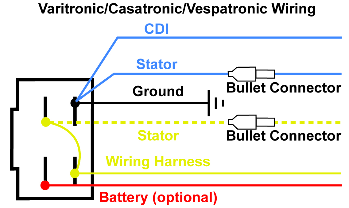
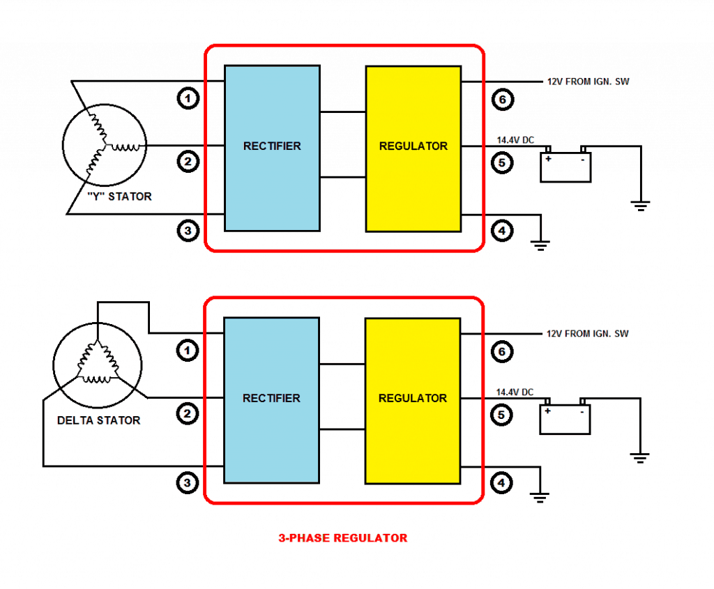
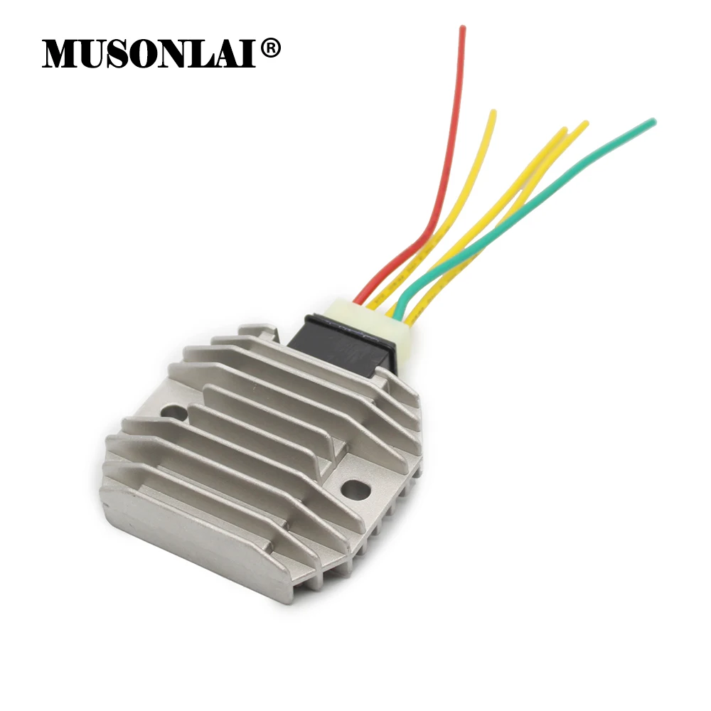
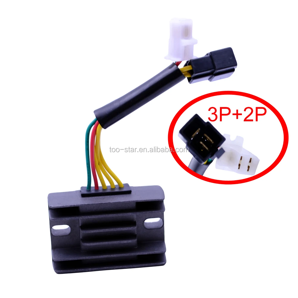
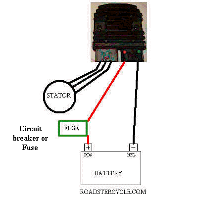
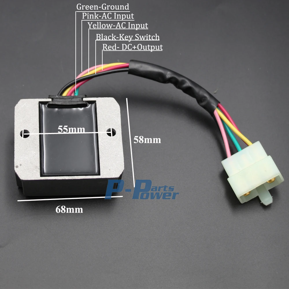
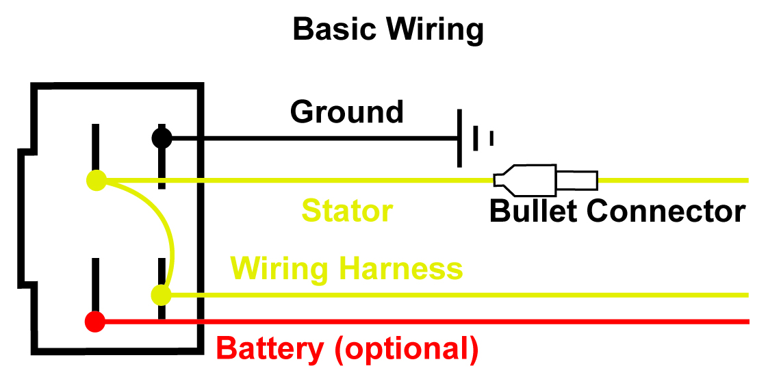
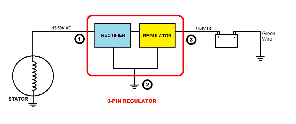
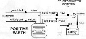
SOLVED: Wiring diagram for voltage regulator: how to wire - Fixya motorcycle rectifier diagram. voltage regulator wiring... Hi, the yellows all come from the alternator, you can connect these in any order to each other, the red wire from the rectifier can be connected directly to the battery, and the black is the earth wire and can be connected to a good ground. Regulator/Rectifier Wire-to-Battery | Adventure Rider Regulator/Rectifier Wire-to-Battery. Here's the inside of the battery box, above, showing the new wiring and the fuse holder. Prior to deviating from the factory wiring I took some voltage measurements across the battery terminals
Rectifier Regulator Wiring Diagram - Wirings Diagram Suzuki Gsxr 600 Fuse Box | Wiring Diagram - Rectifier Regulator Wiring Diagram. The diagram provides visual representation of the electric There are just two things that will be found in almost any Rectifier Regulator Wiring Diagram. The first component is emblem that indicate electric element in...

Regulator rectifier wiring diagram
4 Pin Regulator Rectifier Wiring Diagram - Wiring Diagram Database Honda Regulator Rectifier Wiring Great Installation Of Wiring. Ford Alternator Wiring Diagram Internal Regulator Alternator 1. Wiring Diagram Further 4 Pin Cdi Box On 150cc Gy6 Cdi Wiring Harness. Diode Bridge Rectifier Wiring Diagram For Diagrams Schematics New. Rectifier Regulator Wiring Diagram / DI-Rect Single Phase... John deere a wiring diagram wiring diagram. Rectifier battery + regulator & regulator 12v. In this video, i show how to wire the rectifier/regulator Diagram motorcycle regulator rectifier wiring full version hd quality cjwiring les cafes deric orleans fr 12v or 6v ct70 pigtail click for instructions sub w 12... Alternator Wiring Diagram: A Complete Tutorial | EdrawMax Alternator wiring diagrams are important to simplify the complex connections of an alternator. The rectifier changes the two-way current into a one-way flow-direct current. The voltage then passes on to the voltage regulator that steps up or steps down the voltage to match the needs of different units of...
Regulator rectifier wiring diagram. 6 Wire Regulator Rectifier Wiring Diagram - Wiringpedia 12 12v Rectifier Regulator Diagram Motorcycle Motorcycle Diagram Wiringg Net Motorcycle Wiring Voltage Regulator Electrical Diagram. 110cc Chinese Atv Wiring Diagram Unique Nice 6 Pin Cdi With 110cc Motorcycle Wiring 150cc Scooter 150cc Go Kart. Producing A Fix For The Regulator/rectifier Wiring Issue | Forum VFR TECH. Modifications. Producing A Fix For The Regulator/rectifier Wiring Issue. Facebook. I checked the wiring diagram to be sure there wasn't something designed to make the reading low on purpose….nothing. As a test I jumpered a wire from the positive terminal to the sensor wire…bingo... Full Wave Rectifier-Bridge Rectifier-Circuit Diagram with Design... Bridge Rectifier-Full wave rectifier circuit with diagram & design.Tutorial on full wave bridge rectifier circuit theory,operation & working. The working & operation of a full wave bridge rectifier is pretty simple. The circuit diagrams and waveforms we have given below will help you understand the... Simple Diodeless Rectifier Wiring diagram Schematic Simple Diodeless Rectifier Circuit Diagram. It`s common knowledge that when working with single-supply op amps, implementing simple functions in a bipolar signal environment can be difficult. Sometimes additional op amps and other electronic components are required.
Full Wave Rectifier and Bridge Rectifier Theory Full wave rectifiers have some fundamental advantages over their half wave rectifier counterparts. The average (DC) output voltage is higher than for Another more practical and cheaper alternative is to use an off the shelf 3-terminal voltage regulator IC, such as a LM78xx (where "xx" stands for the... DIY Rectifier Regulator - RIBnet Forums DIY Rectifier Regulator. I'm on my third Yamaha F100 - an engine which I'm prone to sing its praises for reliability, quietness and economy. This is a wiring diagram I tracked down showing a similar 6 wire RR in a bike circuit. Suggestions welcome about handling the black wire as the replacement I... Pitbike Rectifier/Regulator Wiring Diagram - YouTube In this video, I show how to wire the rectifier/regulator to the stator of the pitbike. I show how to make connections for the headlight. I also show how to... 5 Pin Regulator Rectifier Wiring Diagram / Universal 12v 5 Pin Wire... Rectifier regulator wiring diagram for honda motorcycle 6. B+ regulator rectifier & regulator * this diagram shows the early 50cc and 80cc two stroke wiring 5 pin regulator rectifiier wiring diagram sana makatulong po ito sainyo mga bro. The regulator/rectifier prevents the battery from being over...
02 Suzuki Motorcycle Rectifier Wiring Diagram - Wiring Diagram... Burnt Rectifier Wire Help Suzuki Gsx R Motorcycle. Regulator Rectifier Combo With Points Wiring Diagram. Suzuki Wire Diagram Reading Industrial Wiring Diagrams. Wiring Diagram 5 Pin Rectifier Wiring Diagram Jeff. How To Test Voltage Regulator Rectifiers For Motorcycle Atv. Motorcycle Regulator-Rectifier With Low Power Dissipation The fourth regulator I recently purchased is a MOSFET design which is claimed to dissipate less heat and thus be more reliable than the old SCR based designs. To further reduce losses, the MOSFETs do double-duty and act as synchronous rectifiers in the reverse (negative half-cycle) direction for... PDF Chapter 1 | Explanation of Rectifier / regulator wiring * This diagram shows the early 50cc and 80cc two stroke wiring using a five pin connector on the rectifier / regulator. AC is full wave and regulated DC is half wave rectified and regulated Ignition is the self powered CDI type typical on our two stroke scooters. Charging System Diagnostics - Rectifier/Regulator Upgrade This is about replacing the standard equipment Regulator/Rectifier with a more efficient component. Next, examine the wires and connectors between the stator output and the R/R input (three wire harness and connectors) - are these charred/melted due to excessive heating?
Alternator Wiring Diagram: A Complete Tutorial | EdrawMax Alternator wiring diagrams are important to simplify the complex connections of an alternator. The rectifier changes the two-way current into a one-way flow-direct current. The voltage then passes on to the voltage regulator that steps up or steps down the voltage to match the needs of different units of...
Rectifier Regulator Wiring Diagram / DI-Rect Single Phase... John deere a wiring diagram wiring diagram. Rectifier battery + regulator & regulator 12v. In this video, i show how to wire the rectifier/regulator Diagram motorcycle regulator rectifier wiring full version hd quality cjwiring les cafes deric orleans fr 12v or 6v ct70 pigtail click for instructions sub w 12...
4 Pin Regulator Rectifier Wiring Diagram - Wiring Diagram Database Honda Regulator Rectifier Wiring Great Installation Of Wiring. Ford Alternator Wiring Diagram Internal Regulator Alternator 1. Wiring Diagram Further 4 Pin Cdi Box On 150cc Gy6 Cdi Wiring Harness. Diode Bridge Rectifier Wiring Diagram For Diagrams Schematics New.













Comments
Post a Comment