42 3 line diagram
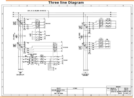
PDF Example Three Line Drawing Components Example Three Line Drawing Components ... - 89L - Meter - Inverters . Title Block 3 Include: - customer name and service address - account and meter number - revision number - date of last revision. DG System Drawing Details 4 Include: - DG type clearly labeled - AC kW nameplate clearly labeled Documenting PV Design - CED Greentech A three line diagram is a complete wiring diagram of the PV system showing all conductors at each circuit segment and connections of these conductors to electrical equipment. Some extremely detailed three lines present connections to electrical equipment at the terminal level.
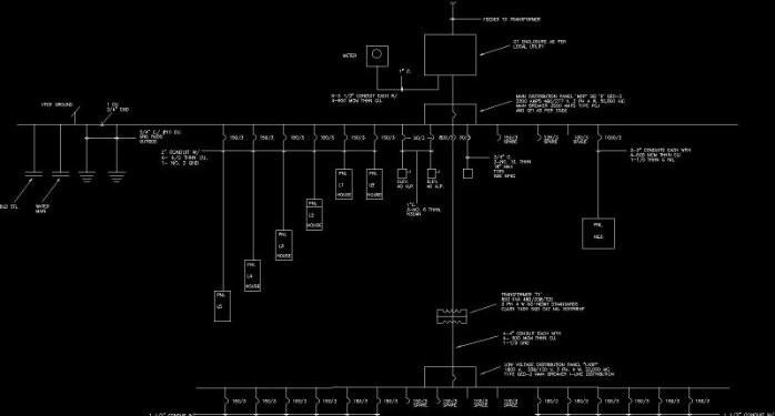
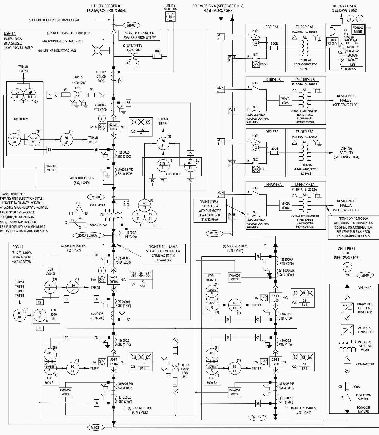
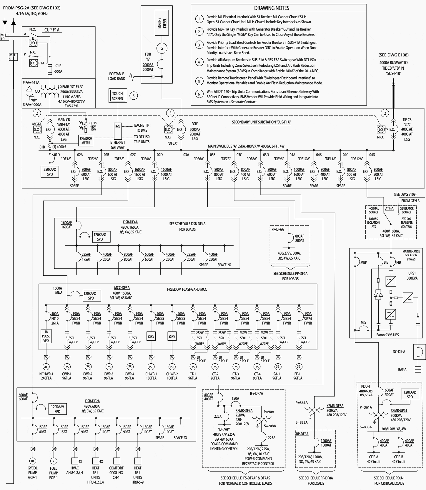
Learn To Interpret Single Line Diagram (SLD) | EEP Single line diagram (SLD) We usually depict the electrical distribution system by a graphic representation called a single line diagram (SLD). A single line can show all or part of a system. It is very versatile and comprehensive because it can depict very simple DC circuits, or a very complicated three-phase system.
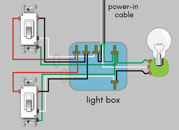
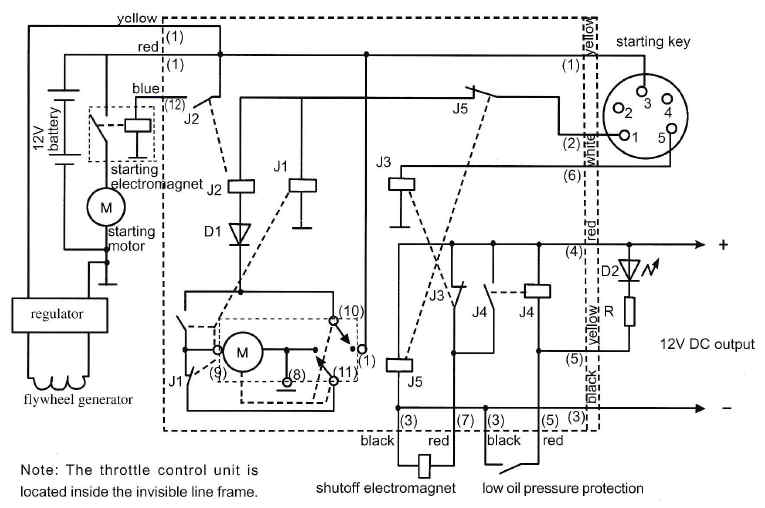
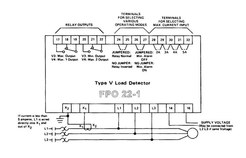
3 line diagram
How to Make a Single Line Diagram — Leaf Electrical Safety Looking at our diagram again we can separate the info into voltage, amperage, and impedance to make sense of what is included for each piece of equipment. Most of this can be found on the equipment nameplates. Voltage The incoming voltage is 12.47 kV and is down to the transformer primary. The transformer steps the voltage down to 600 V. 3 to 8 Line Decoder : Designing Steps & Its Applications 3 to 8 Line Decoder Block Diagram The decoder circuit works only when the Enable pin (E) is high. S0, S1 and S2 are three different inputs and D0, D1, D2, D3. D4. D5. D6. D7 are the eight outputs. The logic diagram of the 3 to 8 line decoder is shown below. 3 to 8 Decoder Circuit 3 to 8 Line Decoder and Truth Table Three-Line Diagram with Enphase Microinverters - Solar ... Three-Line Diagram with Enphase Microinverters 08-13-2010, 11:09 AM. Hi, I'm building my own grid-tied PV system in Massachusetts. One of the requirements to qualify for the rebate is a three-line diagram. Can anyone share an example of a single string 3-line diagram using enphase microinverters? I would greatly appreciate the help.
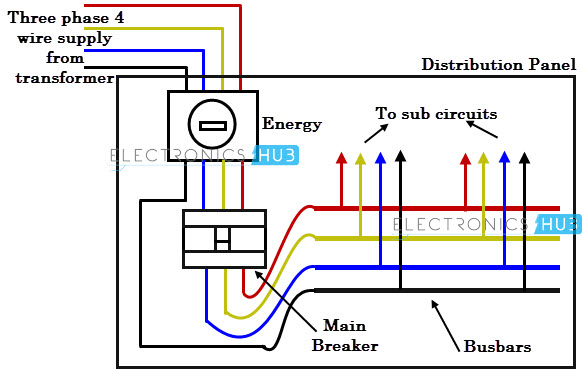
3 line diagram. How to Read a Single Line Diagram | Power Solutions | EECO It will have one single line shown for bus (or cable) to represent all three phases. It will also have symbols that represent breakers, meters, relays, and any other control items that you may have present. It may also include the ANSI protective functions that exist in your equipment. Electrical Three-Line Diagrams - Autodesk Community If this is the main distribution electrical drawing I don't see the need for a three line diagram, or how that would even provide anything of value above a one-line. Further down the line it would make sense for motor controls, etc. More to the point, I would do everything orthogonal with very few exceptions, and then at 45 degrees. PDF Electrical Symbols and Line Diagrams - University of Florida A line (ladder) diagram is a diagram that shows the logic of an electrical circuit or system using standard symbols. A line diagram is used to show the relationship between circuits and their components but not the actual location of the components. Line diagrams provide a fast, easy understanding of the connections and use of components. Electrical Drawings and Schematics Overview - TestGuy Three-line diagrams expand on the single-line by providing a basic visual guide for actual feeder cabling, instrument transformer connections, and protective devices. These drawings show how phases are wired and specific winding configurations without regard for their physical location. Riser Diagram Electrical Riser Diagram. Photo: BGR Engineers.
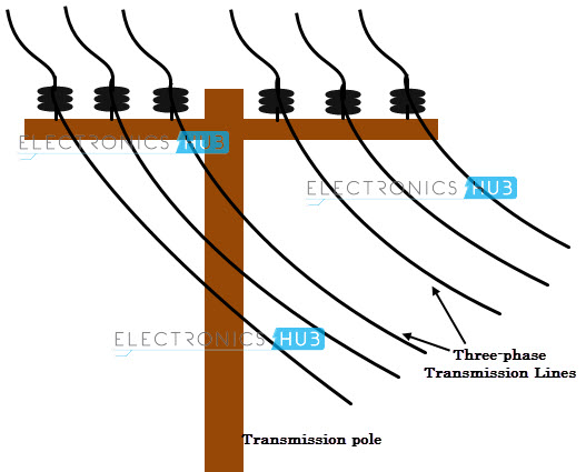
Three Phase Electrical Wiring Installation in Home - NEC & IEC What is Three Phase & Single Phase Power? In power generation plants, Three Phase power is generated by an electrical generator or alternator.In an alternator, the generated voltage and current by three independent coils in the stator are separated by 120 degrees from each other. The generated power from alternators then transmitted and distributed through transmission and distribution lines ... What are the difference between Single Line Diagram (SLD ... 1.Three-line diagram are prepared as a result of further working on the basis of a SLD as they provide details for electrical wiring connections. 2.Three-Line diagram is a part of the detailed design document. 3.Used for control designing circuit diagrams,control circuit,phase sequencing,differential relay setting,metering transformer connection. A One-Line diagram of a three phase system - YouTube As part of your assignment #5 (this is for my students), you have to solve a three phase system represented by its one-line diagram. This clip is about the m... Single Phase & Three Phase Wiring Diagrams (1-Phase & 3 ... With Solved Example. Room Air Cooler Wiring Diagram # 1. Room Air Cooler Wiring Diagram # 2. (With Capacitor marking and Installation) Wiring of the Distribution Board with RCD , Single Phase, (from Energy Meter to the main Distribution Board) Fuse Board Connection. Wiring of the distribution board , Single phase, from Energy meter to the main ...
Three Phase Transformer Connections Phasor Diagrams ... A three-phase transformer is built for a specific connection and voltage transformation and the unit will have a nameplate with the internal connections shown. When a single unit or bank of three is used, there are four types of connections. The four basic connections are: Y-Y, Y-∆, ∆-Y, and ∆-∆. The first symbol indicates the connection of the primary, and the second symbol is the ... Single Line Diagram vs Three line Diagram | Solar Drafting ... Three line diagram is more complicated than a single line or one line diagram. In three line diagram, you need to clearly show the wiring between each PV system components, no matter whether it is DC or AC side of the wiring. In single phase system, you have to show PV+, PV-, PV-G, L1, L2, N, AC Ground connections. Three-Line Diagram? - Physics Forums A three-line diagram is one of the first steps that NYSEG documentation requires to connect to the grid. I've been trying to reach NYSEG, but I figured I'd ask the good PF folks instead of sitting on my hands.) Welcome to the PF. Others will give you better answers, but I'm guessing they mean the 3-phase power wiring diagram? Three-Line Diagram | Line diagram, Single line diagram ... Three-line diagrams expand on the single-line by providing a basic visual guide for actual feeder cabling, instrument transformer connections, and protective devices. These drawings show how phases are wired and specific winding configurations without regard for their physical location. Find this Pin and more on Electrical Engineering by TestGuy.
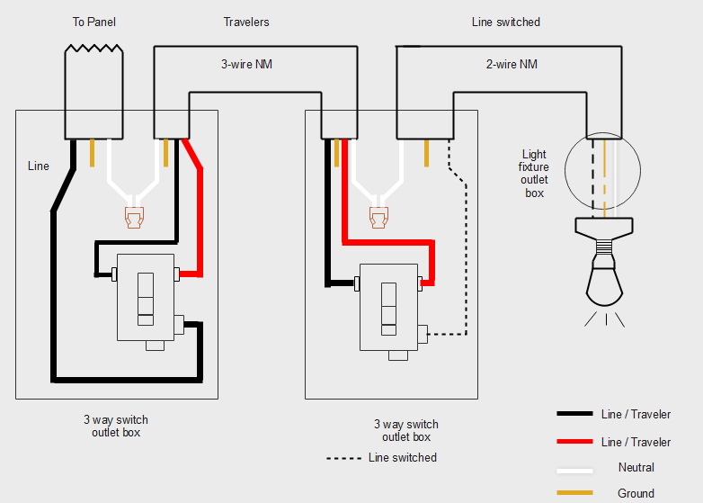
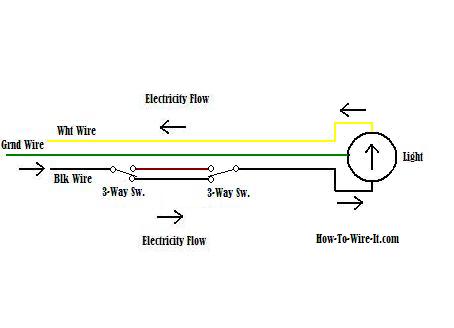
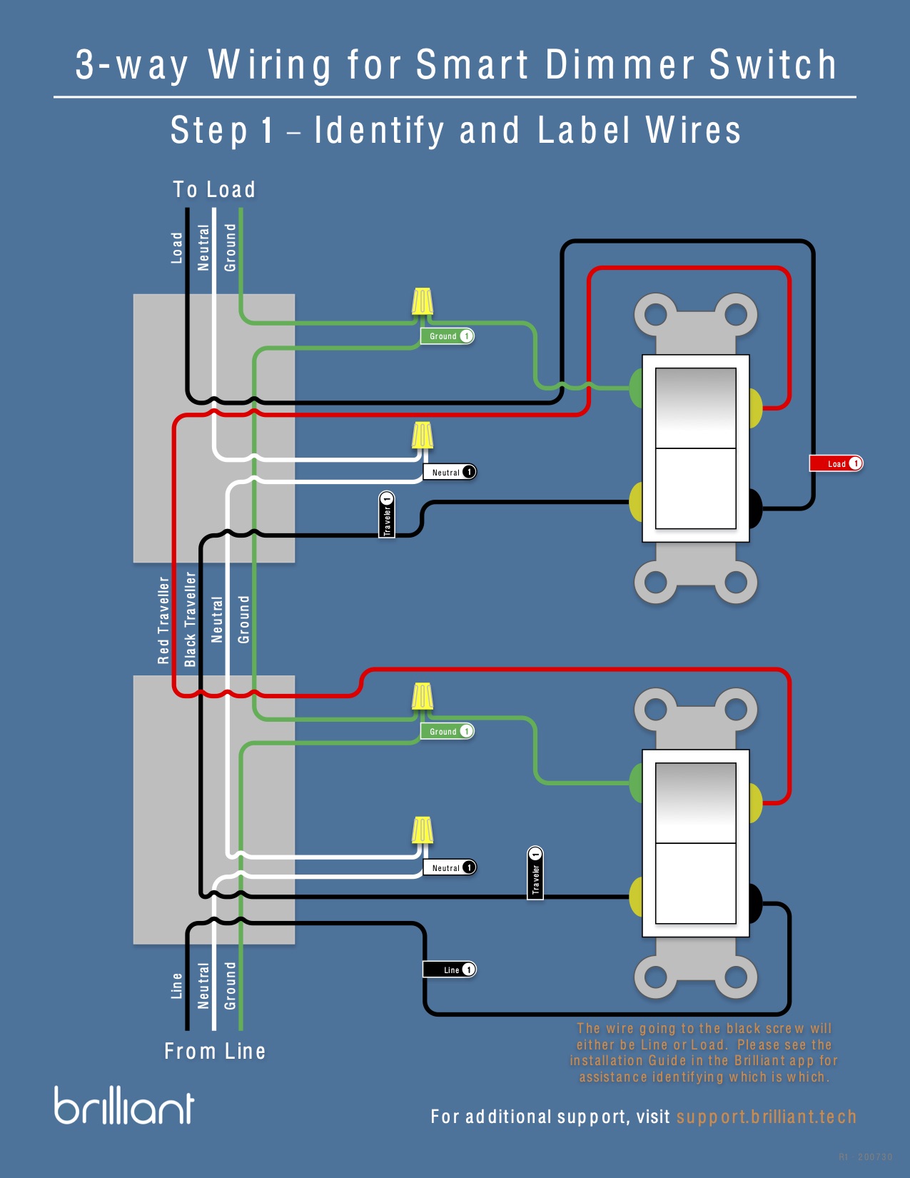
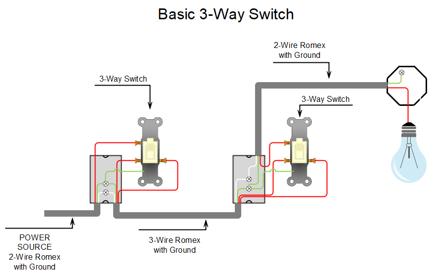
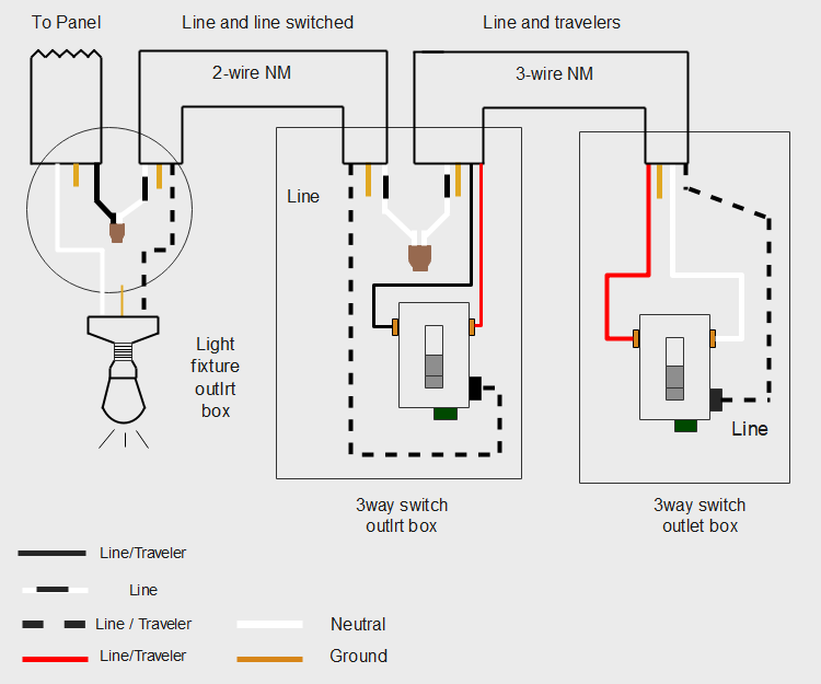
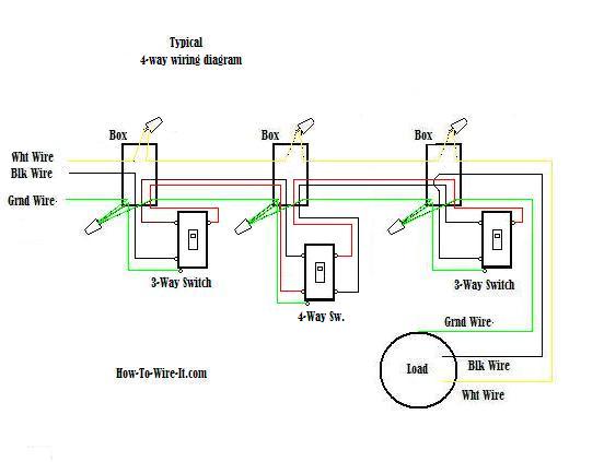
3 Way Switch Wiring Diagram: A Complete Tutorial | EdrawMax 3-Way Switch Wiring Diagram Line to Light Fixture In another configuration, the power supply enters the fixture first, goes into one switch, and finally terminates at the other switch closing the circuit. This wiring diagram helps you understand the type of cables you will require for this configuration. Use EdrawMax for Wiring Diagram Creation
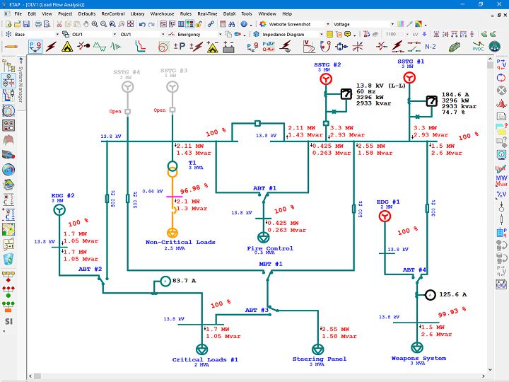
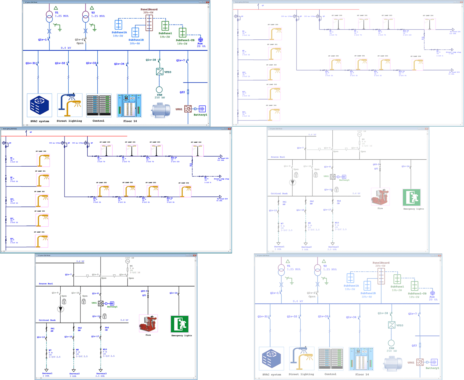
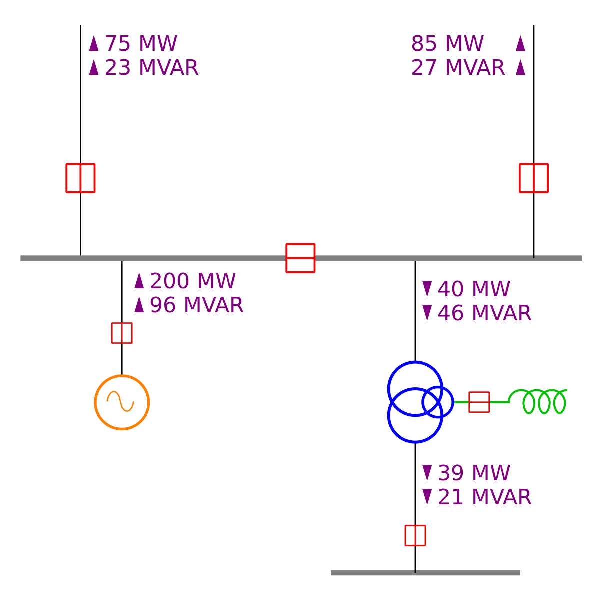
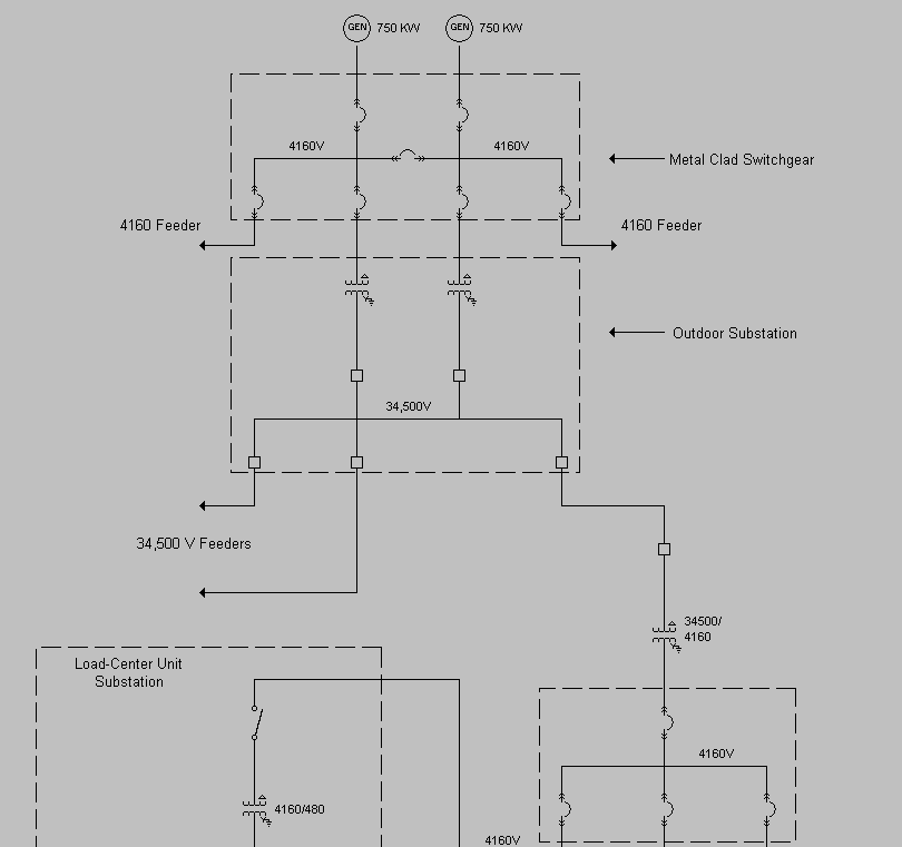
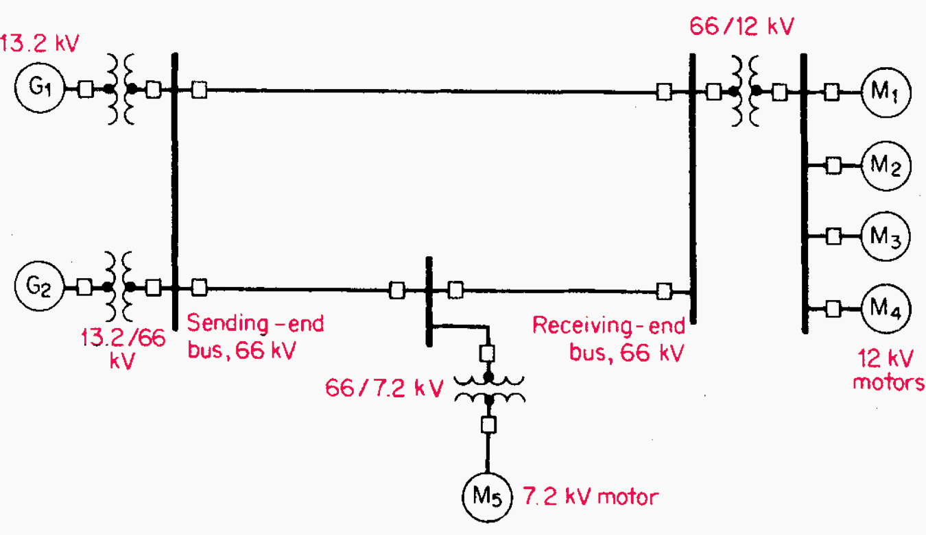
Single-line diagram - Wikipedia In power engineering, a single-line diagram ( SLD ), also sometimes called one-line diagram, is a symbolic representation of a three-phase electric power system. The one-line diagram has its largest application in power flow studies.
Difference Between Single Line Diagram (SLD ) and Three ... Single Line Diagram or One Line Diagram is for basic reference of management and engineers for planning and costing phase of any project. A 3 Line Diagram is for actual implementation during the wiring phase of the project and is often provided to electricians who actually do the cabling.
Single-line Electrical Diagrams | Electric Power ... Single-line diagram representation: Note how much simpler and "cleaner" the single-line diagram is compared to the schematic diagram of the same power system: each three-conductor set of power wires is shown as a single line, each transformer appears as a single primary winding and single secondary winding (rather than three of each), each ...
New to Solar. Help with 3 Line Diagram/ Wiring Diagram ... New to Solar. Help with 3 Line Diagram/ Wiring Diagram. 05-22-2012, 10:04 AM. Hello, I am new to solar but I have been working with someone who has been working with solar for years. He has taught me a lot about solar and I am interested in learning more. Recently he has been trying to get me to study 3-line diagrams because he wants me to be ...
Three line diagram vs one line diagram - CED Greentech On a three line diagram, however, you can see the positive, negative, ground cables of a DC system, and L1, L2, (L3 on three phase) Neutral and Ground cables on an AC system. Each positive and negative line is represented as a single line.
What Is the Difference Between a Single-Line Diagram and a ... Figure 3: A single-line diagram Circuit Diagrams and Wiring Diagrams for Electricians Youth Investigate Trade Skills3 shows a simple one-line diagram. Notice that it contains all the same information as the block diagram in Figure 2, with the addition of some wiring details.
An Example of a 3-line diagram of one section of a main ... The 3-line-diagram ( Figure 1) defines the electrical wiring of the boards. One main switchboard can have over 100 CAD-pages of 3-line diagrams, and the cases that were investigated had thousands...
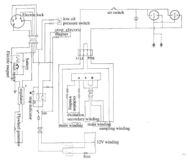
PDF 1-Line and 3-Line Electrical Diagrams - APEC What is a 3-line diagram? Also called a circuit diagram, it shows the connections to each component and every circuit is shown. Also, every electrical component relevant to the system is drawn in this diagram. As a result, a complete 3-line diagram can be used to create a bill of materials for the system.
PDF Typical Electrical Drawing Symbols and Conventions. 1 - master element 2 - time delay starting or closing relay 3 - checking or interlocking relay 4 - master contactor 5 - stopping device 6 - starting circuit breaker 7 - rate of change relay 8 - control power disconnecting device 9 - reversing device 10 - unit sequence switch 11 - multifunction device 12 - overspeed device 13 - synchronous-speed …
How To Calculate and Draw a Single Line Diagram For The ... The completed reactance diagram is shown in Figure 5: TXLs should be j0.13724 (my correction) Figure 5 - Single line reactance circuit diagram (reactances shown on a per-unit basis) 7. Calculate Operating Conditions of the Motors If the motors are operating at 12 kV, this represents 12 kV/13.8 kV = 0.87 per-unit voltage.
Three-Line Diagram with Enphase Microinverters - Solar ... Three-Line Diagram with Enphase Microinverters 08-13-2010, 11:09 AM. Hi, I'm building my own grid-tied PV system in Massachusetts. One of the requirements to qualify for the rebate is a three-line diagram. Can anyone share an example of a single string 3-line diagram using enphase microinverters? I would greatly appreciate the help.
3 to 8 Line Decoder : Designing Steps & Its Applications 3 to 8 Line Decoder Block Diagram The decoder circuit works only when the Enable pin (E) is high. S0, S1 and S2 are three different inputs and D0, D1, D2, D3. D4. D5. D6. D7 are the eight outputs. The logic diagram of the 3 to 8 line decoder is shown below. 3 to 8 Decoder Circuit 3 to 8 Line Decoder and Truth Table
How to Make a Single Line Diagram — Leaf Electrical Safety Looking at our diagram again we can separate the info into voltage, amperage, and impedance to make sense of what is included for each piece of equipment. Most of this can be found on the equipment nameplates. Voltage The incoming voltage is 12.47 kV and is down to the transformer primary. The transformer steps the voltage down to 600 V.









Comments
Post a Comment