41 transmitter block diagram
FM Transmitter Block Diagram with Explanation ... Block diagram of a low level FM broadcast transmitter is shown in figure. The master oscillator generates the RF signal (carrier) required for modulation. Master oscillator is generally a well defined LC oscillator. The buffer amplifier is used to make the oscillator frequency free from the loading of the next stages. PDF Radar Transmitter/Receiver - MIT Lincoln Laboratory Simplified Radar Transmitter/Receiver System Block Diagram • Radar transmitter and receiver can be divided into two important subsystems - High power transmitter sections - Low power sections Radar waveform generator and receiver Duplexer Waveform Generator Receiver High Power Amplifier Filter Low Noise Amplifier A/D 00101111010
PDF Single Sideband Transmitters. - SADARC The above diagram shows a block diagram of SSB generator using the phasing method. This method is less popular due to the complexity of the circuits necessary and the difficulty in tuning the transmitter. It is achieved by placing the unwanted sideband in phase with the required sideband and, as the sidebands

Transmitter block diagram
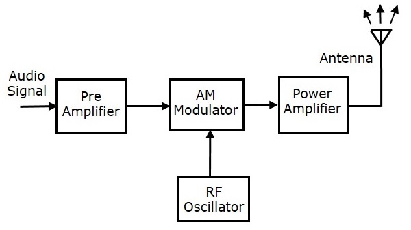
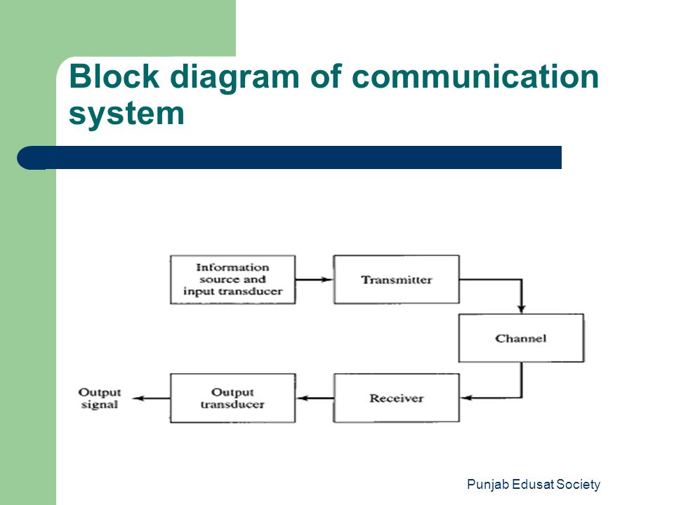
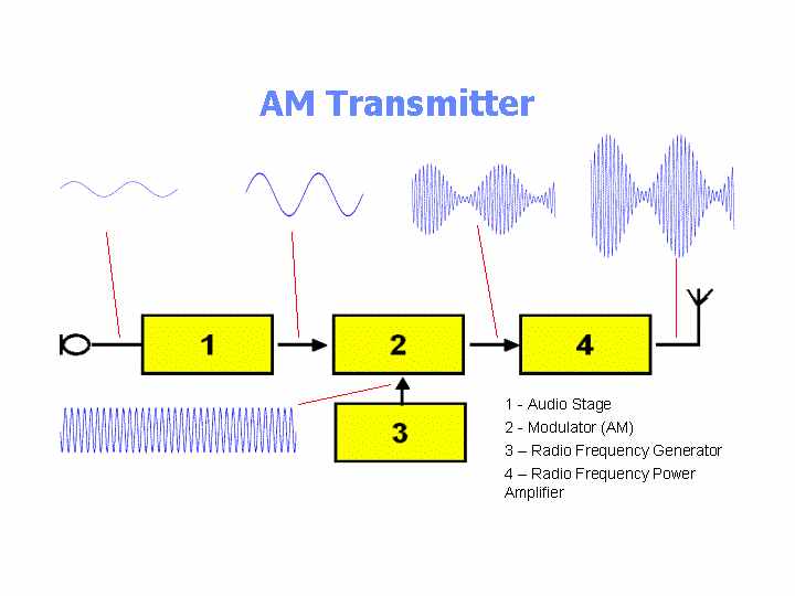
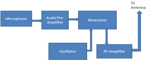
Radio Transmitter Block Diagram - Peter Vis This block diagram of a radio transmitter in a communication system is very simple and basic. It is generalised for AM and FM types of modulation, and consists of four subsystems. Communication is the transfer of meaningful information from one location to another. We start with the conversion of sound waves in the air into electrical energy. Block Diagram of Microwave Transmitter and Receiver ... Block Diagram of Microwave Transmitter and Receiver. The block diagram shows the equipment of a microwave transmitter station on earth. The signal to be transmitter must be at uplink frequency. The converter multiply the signal frequency to uplink frequency after it is encoded and modulated properly. After upconverting the frequency, it is ... Analog Communication - Transmitters - Tutorialspoint The block diagram of AM transmitter is shown in the following figure. The working of AM transmitter can be explained as follows. The audio signal from the output of the microphone is sent to the pre-amplifier, which boosts the level of the modulating signal. The RF oscillator generates the carrier signal.
Transmitter block diagram. Rf remote control switch circuit diagram. - buska.us Infrared remote control circuit transmit signals to devices via radio waves, which is used to control many devices like TV, Radio,Video games etc The block diagram of an IR remote switch consists of two sections: a transmitter section and the other receiver section. Reviews the multiple RFs used today. 0-9. What is Pulse Code Modulation (PCM)? Definition, Block ... The figure below shows the block diagram representing a PCM system It is basically composed of a transmitter, a transmission path and a receiver. The transmitter performs the sampling, quantizing and encoding of the signal. The transmission path includes regenerative receivers that recover the signal from the undesired noise effects. The block diagram of the transmitter. | Download ... IV documents the measurement results, illustrating that the transmit design is realized successfully. Finally, the conclusions are listed in section V. Figure 2 contains the block diagram of the... RF Transceiver : Block Diagram, Working, Specifications ... RF Transceiver Block Diagram RF modules can be applied for various types, sizes, and shapes of electronic circuit boards. It can also be useful for modules across a vast variety of capacities and functionality. These modules typically include a PCB, TX circuit or RX circuit, antenna, and a serial interface for communication to the main processor.
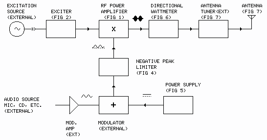
Transmitter Block Diagram - G4PRS RF Power Amplifier. · The power amplification of the radio signal is carried out in the final stage of the block diagram. It makes the signal stronger so that it can be transmitted into the aerial. · The r.f. power amplifier output must be connected to a correctly matched antenna (the "Load") to work properly. Use of the wrong antenna, or ... 4 Block diagram of a QPSK transmitter. 5 shows a block ... 4 Block diagram of a QPSK transmitter. 5 shows a block diagram of a coherent QPSK receiver. The frontend bandpass filter removes the out-of-band noise and adjacent channel interference. PDF TV transmitter and receiver-converted An oversimplified block diagram of a monochrome television transmitter is shown in Fig. The luminance signal from the camera is amplified and synchronizing pulses added before feeding it to the modulating amplifier. Synchronizing pulses are transmitted to keep the camera and the picture tube beams in step. Basic Model of RF Transmitter and Receiver (Part 1/23) Fig. 3: Block Diagram of RF Transmitter and Receiver. Working of Circuit Circuit Connections. As seen from the block diagram, the RF circuit comprises of two sections - : 1) Transmitter section - This section comprises of a HT12E encoder chip, RF transmitter and Antenna are shown below - :
PCM Transmitter Block Diagram - Peter Vis PCM Transmitter Block Diagram Here is a block diagram with explanation of a Pulse Code Modulation (PCM) transmitter. To transmit an analogue signal in digital form, we must first sample it in order to convert it into a digital form. The sampling gate is the block that continuously samples and stores the incoming analogue signal. Block diagram of television transmitter - BrainKart A brief explanation is given ahead. The block diagram can be broadly divided into two -sections, viz., an amplitude modulated transmitter and a frequency modulated transmitter. Former is used for video modulation whereas latter is used for audio modulation. Master oscillator in both generates an RF carrier frequency. PDF A 20Gb/s SerDes Transmitter with Adjustable Source ... Figure 1 shows a high level block diagram of the SerDes transmitter. In this design, a programmable pattern generator is used to generate 8-bit wide pseudo-random data patterns. An 8:2 multiplexer serializes the pattern data into odd and even data streams. The half-rate interleaved transmitter passes AM Transmitters - D&E Notes Figure (b): Block Diagram of Low Level AM Transmitter The low-level AM transmitter shown in the figure (b) is similar to a high-level transmitter, except that the powers of the carrier and audio signals are not amplified. These two signals are directly applied to the modulated class C power amplifier.
Schematic diagram of transmitter and receiver. | Download ...
Block diagram of radio - BrainKart Block diagram of an FM (frequency modulated) transmitter is given on Pic.2.4. Information being transferred, i.e. the modulating signal, is a signal from some LF source. it is being amplified in LF amplifier and then led into the HF oscillator, where the carrier signal is being created.
Analog Communication - Transmitters
PDF TOPIC : TV TRANSMITTER AND RECEIVER Block diagram of ... Block diagram of colour TV transmitter [Q] Draw the block diagram of colour TV transmitter. Describe the function of each block. OR . OR Explanation:- A PAL colour TV transmitter consists of following three main sections. 1. Production of Luminance (Y) and Chrominance (U and V) signals 2. PAL encoder
TX908 Wireless Mouse Transmitter Block Diagram Amended G.Tech ...
PDF Universal Asynchronous Receiver/Transmitter (UART) for ... 1.3 Functional Block Diagram SPRUGP1—November 2010 KeyStone Architecture Universal Asynchronous Receiver/Transmitter (UART) User Guide 1-3 Submit Documentation Feedback Chapter 1—Introduction 1.3 Functional Block Diagram A functional block diagram of the UART is shown in Figure 1-1.
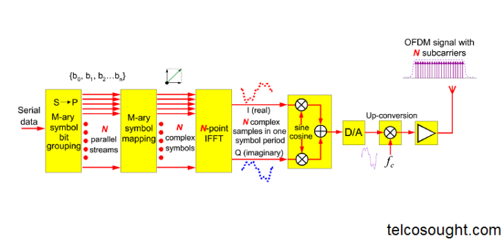
OFDM transmitter and receiver block diagram explanation ...
PDF Basic block diagram of an OFDM - rroij.com simple block diagram of above system is drawn below. s/p IFFT Cyclic prefix p/s D/A Tx s/p A/D Rx Cyclic prefix Removal p/s FFT Basic block diagram of an OFDM noise BPSK Mod. BPSK demod . Fig 1: A simple block diagram of MIMO OFDM System The OFDM system consists of orthogonal subcarriers which carry the modulated symbols. Each OFDM symbol

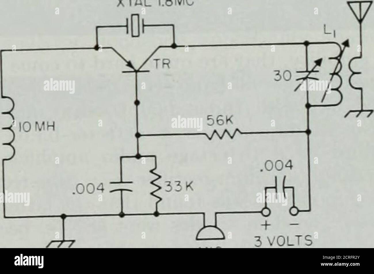
Low Power FM Transmitter
Block diagram of PCM transmitter and receiver. - Ques10 Following is the block diagram of PCM which represents the basic elements of both the transmitter and the receiver sections. Fig2: PCM Transmitter and Receiver Low Pass Filter: This filter eliminates the high frequency components present in the input analog signal which is greater than the highest frequency of the message signal, to avoid ...
QST . pS VOLTS ISUN BATTERYpfg J A block diagram of the solar ...
Radio Transmitter and Receiver | Working | Block Diagram ... A block diagram of a simple continuous wave (CW) transmitter is shown in Figure 6. The first block is the conventional crystal oscillator and then the final power amplifier. A power supply is provided for the oscillator and the final power amplifier. Figure 6. A block diagram representing various stages of a basic continuous wave radio transmitter.
TRANSMITTERS | Home
RF Transmitter and Receiver Circuit using RF Module ... Circuit Diagram of RF Receiver 433MHz RF Receiver Circuit Diagram Circuit Description Transmitter Circuit The HT12E encoder IC VSS pin is connected to the power supply Ground (-) and the VDD is connected to the power supply VCC (+). IC A0 - A7 pins (pin 1 - 8) are connected to the Ground (-) to set the address at 0b00000000.

Arduino FM Transmitter - Engineering Projects
PDF Chapter 4: AM Transmitters - N0GSG Figure 4-1: Low Level AM Transmitter Block Diagram There are two signal paths in the transmitter, audio frequency (AF) and radio frequency (RF). The RF signal is created in the RF carrier oscillator. At test point A the oscillator's output signal is present.
LECTURE ON AM/FM TRANSMITTER - ppt download
RF Transceiver Module With Block Diagram Explanation Block Diagram of RF Transceivers In general, the designer of wireless systems has two overriding limitations: it must work over a convinced distance and transfer a convinced amount of information within a data rate. The size of the RF modules is very small and have an extensive range of a operating voltage that is 3V to 12V.

1 — Transmitter functional block diagram | Download ...
Block Diagrams for RF and Microwave Systems - Pasternack Pasternack's library RF and microwave block diagram are designed to provide engineers and designers with examples of common RF systems schematics while illustrating the RF products and where they fit into the system's design.
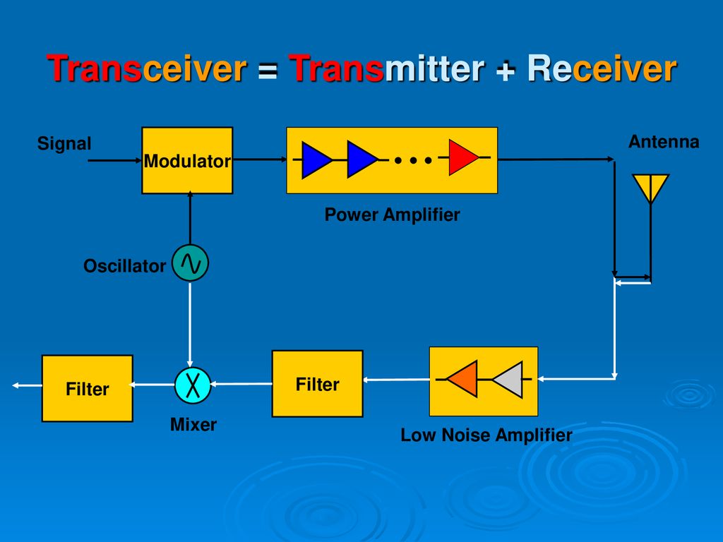
Transceiver Block Diagram - ppt download
Analog Communication - Transmitters - Tutorialspoint The block diagram of AM transmitter is shown in the following figure. The working of AM transmitter can be explained as follows. The audio signal from the output of the microphone is sent to the pre-amplifier, which boosts the level of the modulating signal. The RF oscillator generates the carrier signal.

Long range fm transmitter circuit,2 km 88-108 MHz VHF
Block Diagram of Microwave Transmitter and Receiver ... Block Diagram of Microwave Transmitter and Receiver. The block diagram shows the equipment of a microwave transmitter station on earth. The signal to be transmitter must be at uplink frequency. The converter multiply the signal frequency to uplink frequency after it is encoded and modulated properly. After upconverting the frequency, it is ...

Transmitter vs Receiver | Transmitter types,Receiver types ...
Radio Transmitter Block Diagram - Peter Vis This block diagram of a radio transmitter in a communication system is very simple and basic. It is generalised for AM and FM types of modulation, and consists of four subsystems. Communication is the transfer of meaningful information from one location to another. We start with the conversion of sound waves in the air into electrical energy.

Downlink Multicarrier Transmitter Test - ADS 2009 - Keysight ...

4-20mA Current Loop Transmitter - Renesas | Mouser

Explain Delta modulator transmitter and receiver with neat ...

Satellite Earth Station Block Diagram
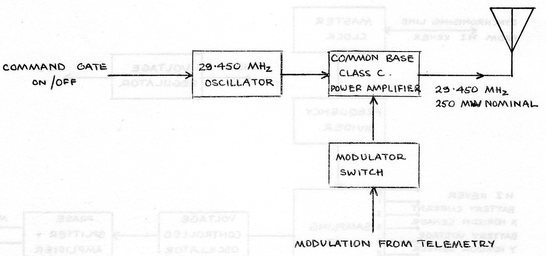
HF Transmitter

Transmitter vs Receiver | Transmitter types,Receiver types ...

Power Consumption: a Primary Consideration in Smart ...

Block diagram and operation of transmitter unit of mobile ...

Draw the block diagram of Amplitude Modulated (AM) Radio ...
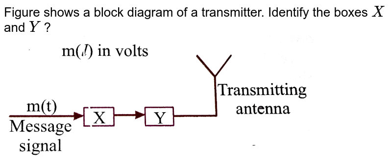
Figure shows a block diagram of a transmitter. Identify the ...

AM Transmitters
PCM Transmitter Block Diagram

Block diagram of the RF transmitter | Download Scientific Diagram

Communication Protocols Assignments: Block diagram of AM ...

Figure shows a block diagram of a transmitter. Identify the boxes X and Y ?

802.11ac Transmitter Block
Envelope Tracking Circuit Block Diagram » Electronics Notes
A.M. Transmitter Tutorial - AM Transmitters - Block Diagrams ...

FM Transmitter Block Diagram, Working Principle Understand ...
Class E AM Transmitter for 1710 kHz - Circuit Description and ...
Transmitter Block Diagram

SR119 Remote Control Transmitter Block Diagram Nuzon ...

Smart Instruments and Systems - AONG website

High Power FM Transmitter Project - DIY

Figure 3. Block diagram of the optical transmitter : Inter ...
FM Transmitter Circuit Working and Its Applications

With the functional block diagram explain the working of a ...
transmitter | electronics | Britannica


Comments
Post a Comment