42 pure sine wave inverter circuit diagram free download
Sine Wave Inverter Circuit Diagram - insys.fsu.edu sine-wave-inverter-circuit-diagram 1/1 Downloaded from insys.fsu.edu on February 12, 2022 by guest [DOC] Sine Wave Inverter Circuit Diagram This is likewise one of the factors by obtaining the soft documents of this sine wave inverter circuit diagram by online. PDF Sine Wave Inverter Circuit Diagram - wlu.wickedlocal.com Make This 1KVA (1000 watts) Pure Sine Wave Inverter Circuit sine wave inverter circuit diagram with complete step by step program and coding, In this article I will discuss how to use push pull converter, sinusoidal pulse width modulation, h bridge and low pass LC filter to make pure sine wave inverter circuit diagram.
Make This 1KVA (1000 watts) Pure Sine Wave Inverter Circuit A relatively simple 1000 watt pure sine wave inverter circuit is explained here using a signal amplifier and a power transformer. As can be seen in the first diagram below, the configuration is a simple mosfet based designed for amplifying current at +/-60 volts such that the connected transformer corresponds to generate the required 1kva output.

Pure sine wave inverter circuit diagram free download
Sine Wave Inverter Driver Circuit Nov 05, 2012 · Pure Sine-Wave Inverter. Pure Sine wave inverter consist of a microcontroller unit which generates a switching signal of 15 KHz, an H-bridge circuit to convert the signal into AC, a low pass LC filter circuit to block the high frequency components and the transformer unit to step-up the voltages. DIY Cheap 1000W Pure Sine Wave Inverter (12V to 110V/220V ... DIY Cheap 1000W Pure Sine Wave Inverter (12V to 110V/220V): Car batteries for powering you home? Build a low cost 12V to 220V (DC-AC) Pure Sine Wave Inverter from scratch! The project is based on the low cost EGS002 SPWM driver board module. The DIY inverter board can handle up to 1kW (depending the transfor… Pure sine wave inverter design and circuit | Forum for ... 230V, 50Hz, 1.5KVA, Full bridge pure sine wave inverter circuit using sinusoidal pulse width modulation. I have included circuit diagram using IGBT, PIC18F886 circuit diagram, Assembly language program for PIC16F886 and HEX file in PDF format.
Pure sine wave inverter circuit diagram free download. Pure sine wave inverter circuit diagram free download ... An Inverter Not Only Converts The Dc Voltage Of Battery To v V Ac Signals But Also Charge The Battery When The Ac Mains Is Present - Pure Sine Wave Inverter Circuit Diagram Free Download. China Battery Inverter Dc 12 V Ac Peak w Pure Sine Wave Circuit Diagram Solar Pv Power. 5kva Ferrite Core Inverter Circuit Full Working Diagram With ... Pure Sine Wave Inverter Schematics Free !NEW! ⚡ - Coub Coub is YouTube for video loops. You can take any video, trim the best part, combine with other videos, add soundtrack. It might be a funny scene, movie quote, animation, meme or a mashup of multiple sources. Simple Sinewave Inverter Circuits - Making Easy Circuits The following is a high efficiency sine wave inverter electrical diagram, the circuit with 12V battery-powered. First with a double voltage module voltage for the op amp power supply. The ICL7660 or MAX1044 can be selected. Op Amp 1 generates a 50 Hz sine wave as the reference signal. Op amp 2 as an inverter. PDF Low Cost Pure Sine Wave Solar Inverter Circuit A pure sine wave is highly desirable because the vast majority of electrical plug-in appliances are designed to run on a true sine wave signal. This is accomplished through an inverter circuit using electronic components. Two types of inverters currently exist on the market; a modified sine-wave inverter and a pure sine wave inverter.
Pure Sine Wave Inverter Schematics Free //FREE\\ - Coub Coub is YouTube for video loops. You can take any video, trim the best part, combine with other videos, add soundtrack. It might be a funny scene, movie quote, animation, meme or a mashup of multiple sources. PURE SINE WAVE INVERTER PROJECT - Instructables PURE SINE WAVE INVERTER PROJECT: TECHNICAL SPECIFICATIONS: VOLTAGE LIMITS (INVERTER MODE) : Mains A.C. Lower Voltage Limit :110+ 5V Lower Recovery Voltage :120+ 5V Mains A.C. Higher Voltage Limit : 275+ 5V Higher Recovery Voltage : 265+ 5V Output Voltage in Inverter Mod… Pic12f683 inverter circuit with project file download Pic12f683 inverter circuit with project file download. today i am sharing is a project i am working on which is pic12f683 pure sine wave inverter project and this project was created by hung pham and i and most of is subscribers are interested in the project, but the project as some issues, most think is the software but it is a big NO, the ... (PDF) Sine Wave Home Inverter - researchgate.net But the sine wave inverters are costly than other inverters. So we try to make an inverter which output is nearly pure sine wave. Inverter is the DC to AC voltage conversion. In our project we ...
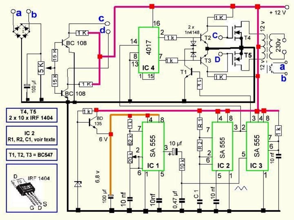
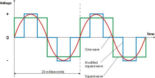
PDF Circuit Diagram For Inverter Design Basic Inverter - Schematic Design - Electronic Circuit Diagram Modified Sine wave Inverter Circuit Diagram The circuit consists of IC 555 which is tuned to generate frequency at 200Hz (square wave) at 50% duty cycle. The square wave is fed to IC 4017 which will convert to modified sine wave at 50Hz at 50% duty cycle. IC 555 frequency calculation: Download Sukam Sine Wave Inverter Circuit Diagram 800Va ... Download Sukam Sine Wave Inverter Circuit Diagram 800Va Pics. Pic codes can be viewed here. 800va pure sine wave inverter s reference design 7. Sukam Sinewave Inverter Diagram Smd And Old And Microcontroller Pin Details With Falut Finding Youtube from i.ytimg.com 800va pure sine wave inverter s reference design 7. I want to tell you that pure sine wave inverter schematic have some mistakes ... PDF DC/AC Pure Sine Wave Inverter output generated: modified sine wave, and pure sine wave1. A modified sine wave can be seen as more of a square wave than a sine wave; it passes the high DC voltage for specified amounts of time so that the average power and rms voltage are the same as if it were a sine wave. Report: DC/AC Pure Sine Wave Inverter - Schematic Design Report: DC/AC Pure Sine Wave Inverter. Here the project report of DC/AC pure sine wave inverter. This report focuses on DC to AC electrical power inverters, which aim to efficiently transform a DC power source to a high voltage AC supply, just like electrical power that would be presented at an electrical wall outlet.
Homemade 2000w power inverter with circuit diagrams - GoHz (Download PDF file) SPWM driver board circuit, EG8010 + IR2110, to detect the voltage drop for short circuit protection. (Download PDF file) Related paper: Car Power Inverter Buying Guide. Buying a pure sine wave inverter on GoHz.com, 300w inverter, 500w inverter, 1000w inverter...
1000W DC AC Pure Sine Wave Power Inverter Circuit Diagram This circuit is a pulse oximeter , it is a medical device to indirectly measure the amount of oxygen in the blood of a person . The circuit is very simple and inexpensive to build , the sensor to be monitored only need an oscilloscope , but the case does not have an oscilloscope , here an article on how to make your pc a Oscilloscope .
Pure Sine Wave Inverter Design With Code - The Engineering ... Pure Sine-Wave Inverter. Pure Sine wave inverter consist of a microcontroller unit which generates a switching signal of 15 KHz, an H-bridge circuit to convert the signal into AC, a low pass LC filter circuit to block the high frequency components and the transformer unit to step-up the voltages. Block diagram of sine wave circuit is given below:
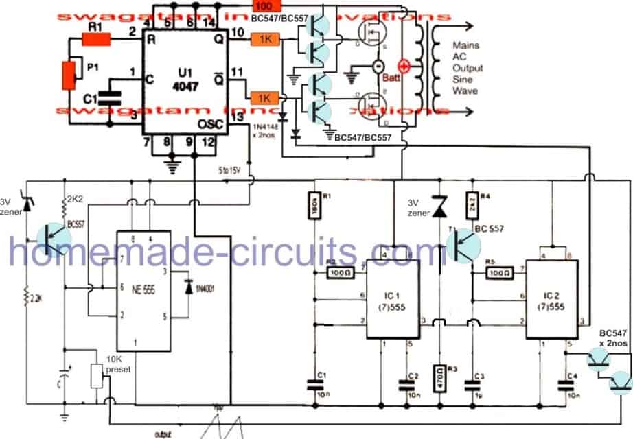
3 High Power SG3525 Pure Sinewave Inverter Circuits ... Circuit Design#2: In the above section we learned the basic version of IC SG3525 designed to produce a modified sine wave output when used in an inverter topology, and this basic design cannot be enhanced to produce a pure sinewave waveform in its typical format.. Although the modified squarewave or sinewave output could be OK with its RMS property and reasonably suitable for powering most ...
Pure Sine Wave Inverter (12v/24v/48v) | inverter.com 300 Watt Pure Sine Wave UPS Inverter. SKU: ATO-UPSI-300. High efficiency 333VA pure sine wave ups inverter for sale, DC input voltage can select 12V, 24V, 48V, with uninterruptible power source, output frequency 50Hz or 60Hz, short circuit and over temperature protection. Price: From $222.44.
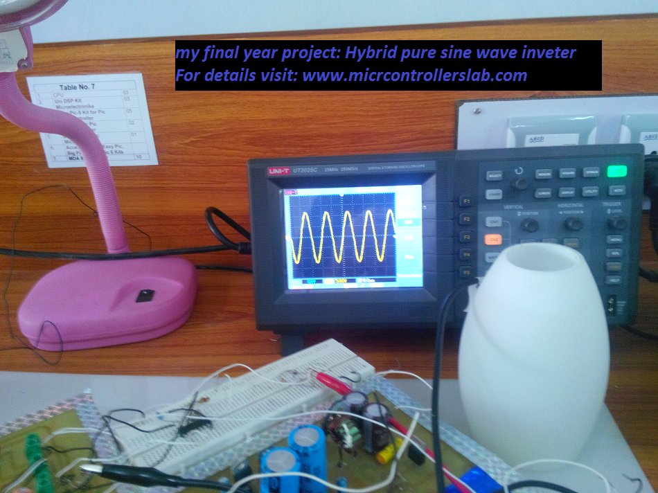
pure sine wave inverter circuit diagram - Microcontrollers Lab I have got pure sine wave in my final year project " hybrid pure sine wave inverter " after connecting a LC filter at the output of H Bridge.I have LC values L= 2mH and C= 3.3uf .Diagram of pure sine I have got in my final year project is shown in figure below: pure sine wave inverter implementation and circuit diagram
PDF PWM Techniques: A Pure Sine Wave Inverter encodes a sine wave. The duty cycle of the output is changed such that the power transmitted is exactly that of a sine-wave. This output can be used as-is or, alternatively, can be filtered easily into a pure sine wave. This report documents the design of a true sine wave inverter, focusing on the inversion of a DC high-voltage source.
PDF Inverter Circuit With Pic16f72 - meet.soh.hku.hk Sinewave UPS Circuit Using PIC16F72 Power Inverter Mosfet. PIC16F72 Code And Schematic For Sine Wave Inverter. DC AC Pure Sine Wave Inverter. Sine Wave Inverter Circuit Diagram With Full Explanation. Pekerjaan Tenaga Kerja Square Wave Inverter Using. Inverter Circuit Diagram Using Pic16f72 PDF Download. Inverter Circuit With Pic16f72 Genews De.
Pure Sine Wave Inverter Circuit Using Arduino Pure Sine Wave Inverter Using Arduino. Arduino. By Debashis Das Aug 28, 2020 3. Inverter circuits are often needed where it is not possible to get AC supply from the grid. An inverter circuit is used to convert DC power to AC power and it can be divided into two types that is Pure Sine Wave Inverters or Modified Square Wave Inverters.
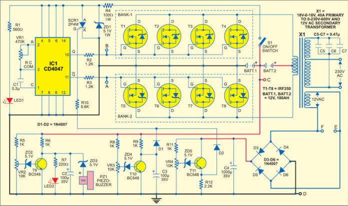
Make your own Sine Wave Inverter | Full Inverter Circuit ... The project is a simple sine wave inverter circuit that produces 50Hz quasi-sine wave output using a single IC CD4047 and some discrete components, which makes it a very cost-effective solution. Sine wave inverter circuit description. Fig. 1 shows the sine wave inverter circuit of the MOSFET-based 50Hz inverter.
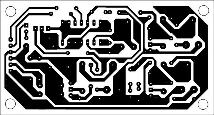
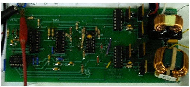
Sine Wave Inverter Circuit using PIC16F72 The close up of the mother board of the proposed sinewave inverter using PIC16F72 can be witnessed in the following image. This picture shows the PCB track layout for the proposed inverter design. Hex files and PIC code along with PCB designs of this pure sine wave inverter circuit using PIC16F72 can be downloaded from the above shown links ...
Pure sine wave inverter design and circuit | Forum for ... 230V, 50Hz, 1.5KVA, Full bridge pure sine wave inverter circuit using sinusoidal pulse width modulation. I have included circuit diagram using IGBT, PIC18F886 circuit diagram, Assembly language program for PIC16F886 and HEX file in PDF format.
DIY Cheap 1000W Pure Sine Wave Inverter (12V to 110V/220V ... DIY Cheap 1000W Pure Sine Wave Inverter (12V to 110V/220V): Car batteries for powering you home? Build a low cost 12V to 220V (DC-AC) Pure Sine Wave Inverter from scratch! The project is based on the low cost EGS002 SPWM driver board module. The DIY inverter board can handle up to 1kW (depending the transfor…
Sine Wave Inverter Driver Circuit Nov 05, 2012 · Pure Sine-Wave Inverter. Pure Sine wave inverter consist of a microcontroller unit which generates a switching signal of 15 KHz, an H-bridge circuit to convert the signal into AC, a low pass LC filter circuit to block the high frequency components and the transformer unit to step-up the voltages.










![SOLVED] - Pure Sine Wave Inverter Design | Forum for Electronics](https://i.imgur.com/QpX93md.png)


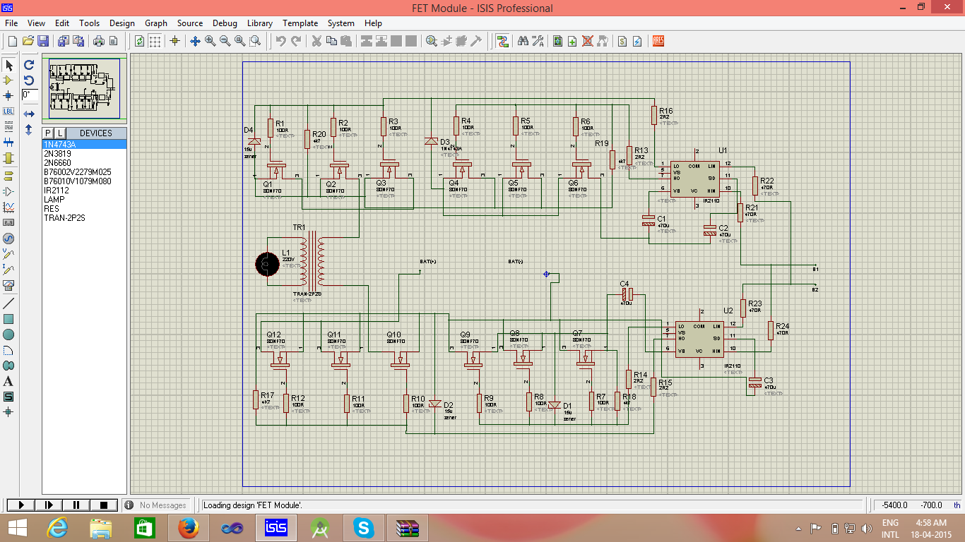


Comments
Post a Comment